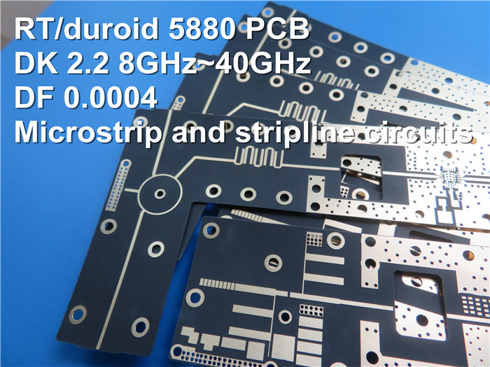
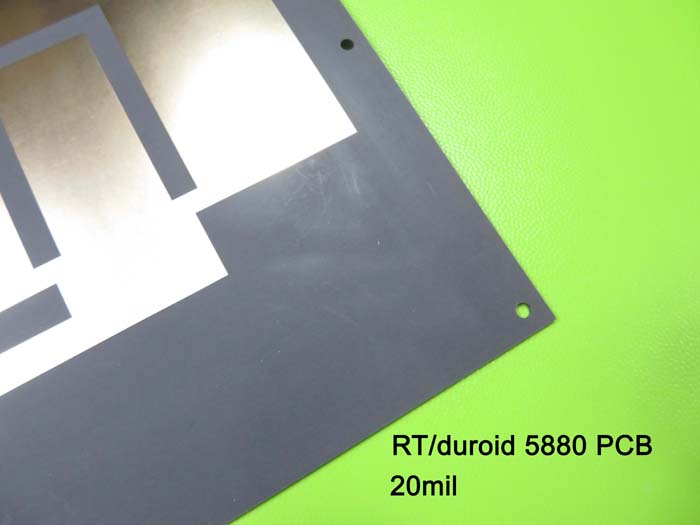
RT/Duroid
5880 20mil 0.508mm Rogers High Frequency PCB for Radar Systems
(Printed
Circuit Boards are custom-made products, the picture and parameters shown are
just for reference)
Rogers
RT/duroid 5880 high frequency materialis glass microfiber reinforced PTFE
composites which is designed for exacting stripline and microstrip circuit
applications. The exceptional dielectric constant uniformity results from its
randomly oriented microfibers. The dielectric constant of RT/duroid 5880 is
uniform from panel to panel and is constant over a wide frequency range. Its low dissipation factor extends the usefulness of RT/duroid 5880 to Ku-band and
above. RT/duroid 5880 materials are easily cut, sheared and machined to shape.
They are resistant to all solvents and reagents, hot or cold, normally used in etching printed circuits or in plating edges and holes.
The
typical applications are commercial airline broadband antennas, microstrip
circuits, stripline circuits, millimeter wave applications, military radar
systems, missile guidance systems and point to point digital radio antennas
etc.

Basic specifications:
Base
material: RT/duroid 5880 20mil (0.508mm)
Dielectric
constant: 2.20+/-0.02
Layer
count: 2 layers
Type:
Through holes
Format:
128mm x 62mm = 1 type = 1 piece
Surface
finish: Immersion gold
Copper
weight: Outer layer 35 μm
Solder
mask | Legend: No | No
Final
PCB height: 0.52 mm
Standard:
IPC 6012 Class 2
Packing:
20 panels are packed for shipment.
Lead
time: 7 working days
Shelf
life: 6 months
Data
sheet of Rogers RT/duroid 5880:
|
RT/duroid 5880 Typical Value
|
|
Property
|
RT/duroid 5880
|
Direction
|
Units
|
Condition
|
Test Method
|
|
Dielectric
Constant,εProcess
|
2.20
2.20±0.02 spec.
|
Z
|
N/A
|
C24/23/50
C24/23/50
|
1 MHz
IPC-TM-650 2.5.5.3
10 GHz IPC-TM 2.5.5.5
|
|
Dielectric Constant,εDesign
|
2.2
|
Z
|
N/A
|
8GHz to 40 GHz
|
Differential Phase
Length Method
|
|
Dissipation Factor,tanδ
|
0.0004
0.0009
|
Z
|
N/A
|
C24/23/50
C24/23/50
|
1
MHz IPC-TM-650 2.5.5.3
10 GHz IPC-TM 2.5.5.5
|
|
Thermal Coefficient of ε
|
-125
|
Z
|
ppm/℃
|
-50℃to 150℃
|
IPC-TM-650 2.5.5.5
|
|
Volume Resistivity
|
2 x
107
|
Z
|
Mohm cm
|
C/96/35/90
|
ASTM D 257
|
|
Surface Resistivity
|
3 x 10⁷
|
Z
|
Mohm
|
C/96/35/90
|
ASTM D 257
|
|
Specific Heat
|
0.96(0.23)
|
N/A
|
j/g/k
(cal/g/c)
|
N/A
|
Calculated
|
|
Tensile Modulus
|
Test
at 23℃
|
Test
at 100℃
|
N/A
|
MPa(kpsi)
|
A
|
ASTM D 638
|
|
1070(156)
|
450(65)
|
X
|
|
860(125)
|
380(55)
|
Y
|
|
Ultimate Stress
|
29(4.2)
|
20(2.9)
|
X
|
|
27(3.9)
|
18(2.6)
|
Y
|
|
Ultimate Strain
|
6
|
7.2
|
X
|
%
|
|
4.9
|
5.8
|
Y
|
|
Compressive Modulus
|
710(103)
|
500(73)
|
X
|
MPa(kpsi)
|
A
|
ASTM D 695
|
|
710(103)
|
500(73)
|
Y
|
|
940(136)
|
670(97)
|
Z
|
|
Ultimate Stress
|
27(3.9)
|
22(3.2)
|
X
|
|
29(5.3)
|
21(3.1)
|
Y
|
|
52(7.5)
|
43(6.3)
|
Z
|
|
Ultimate Strain
|
8.5
|
8.4
|
X
|
%
|
|
7.7
|
7.8
|
Y
|
|
12.5
|
17.6
|
Z
|
|
Moisture Absorption
|
0.02
|
N/A
|
%
|
0.62"(1.6mm)
D48/50
|
ASTM D 570
|
|
Thermal Conductivity
|
0.2
|
Z
|
W/m/k
|
80℃
|
ASTM C 518
|
|
Coefficient of Thermal Expansion
|
31
48
237
|
X
Y
Z
|
ppm/℃
|
0-100℃
|
IPC-TM-650 2.4.41
|
|
Td
|
500
|
N/A
|
℃TGA
|
N/A
|
ASTM D 3850
|
|
Density
|
2.2
|
N/A
|
gm/cm3
|
N/A
|
ASTM D 792
|
|
Copper Peel
|
31.2(5.5)
|
N/A
|
Pli(N/mm)
|
1oz(35mm)EDC
foil
after solder float
|
IPC-TM-650 2.4.8
|
|
Flammability
|
V-0
|
N/A
|
N/A
|
N/A
|
UL 94
|
|
Lead-free Process Compatible
|
Yes
|
N/A
|
N/A
|
N/A
|
N/A
|
Applications:
Commercial
Airline Broadband Antennas, Microstrip and Stripline Circuits, Millimeter Wave
Applications, Military Radar Systems, Missile Guidance Systems, Point to Point
Digital Radio Antennas.

PCB MANUFACTURING PROCESS:

BICHENG PCB WORKSHOP:

BICHENG PCB CERTIFICATE:

BICHENG MAIN COURIERS:
